
Sponsored by Pickering Interfaces.
The next power architecture of choice for EVs is 800 V, which requires components to be suitably rated and more durable than their 400 V counterparts. However, most test equipment used for 400 V EV system development can be re-used for 800 V if it can handle the higher voltages, making the transition easier for EV developers.
Download the white paper for further information
The Benefits of Hardware-in-the-Loop and Simulation
In EV development, many companies use Hardware-in-the-Loop (HIL) Simulation as part of a test-driven strategy. HIL simulation allows hardware, such as a Battery Management System (BMS), to interact with a simulated environment that mimics real-world conditions, including physical factors like temperature and dynamic conditions like motion and vibration. This helps engineers observe system behavior under realistic scenarios.
Simulating these real-world conditions enables early identification of design flaws and weaknesses, allowing for timely improvements and avoiding costly issues later in development. A key advantage of simulation in EV development is the ability to safely create extreme fault conditions—such as rapid discharging and short circuits—to evaluate BMS behavior without risking damage to actual battery packs.
Creating a HIL Test Platform
While a HIL test platform could be created from scratch, the cost (both monetary and time) of doing so tends to be prohibitive in the automotive industry. Therefore, the use of an industry-standard platform is highly recommended. Two standards to consider are PXI and LXI, which are based on the PCI and Ethernet industry standards, respectively.
Both are supported by a large number of global vendors with many commercial off-the-shelf products available. Both provide seamless vendor-independent plug-and-play. Of great benefit is that product longevity is assured, and the vendors have obsolescence management processes in place.
400 to 800 V Testing Migration Path
Many OEMs and systems houses in the automotive sector have invested in development and verification equipment, including HILS systems, for EVs. The good news for those using PXI or LXI platforms is that many existing modules will still be usable when transitioning from a 400 V to an 800 V architecture, allowing for significant reuse of the test system.
For components that need replacement due to higher voltage ratings, PXI and LXI’s modularity and scalability make it easy to swap them out for upgraded versions.
Below, we discuss a few Pickering Interfaces products suitable for use in 800V architectures.
Battery Cell Simulation
Cell-level simulation is essential for EV development, as it allows the Battery Management System (BMS) to recognize a fully charged pack accurately. This requires simulating individual 3.2 to 3.7 V cells and stacking them to achieve the necessary voltage—96 cells for 400 V and 192 cells for 800 V.
The BMS also manages cell balancing, necessitating the ability to simulate each cell’s charge level during rest, charging, discharging, and introducing imbalances.
By simulating cells independently, existing equipment can be adapted for 400 V and 800 V architectures by adding more modules (simulated cells) as long as the emulator can handle higher voltages.
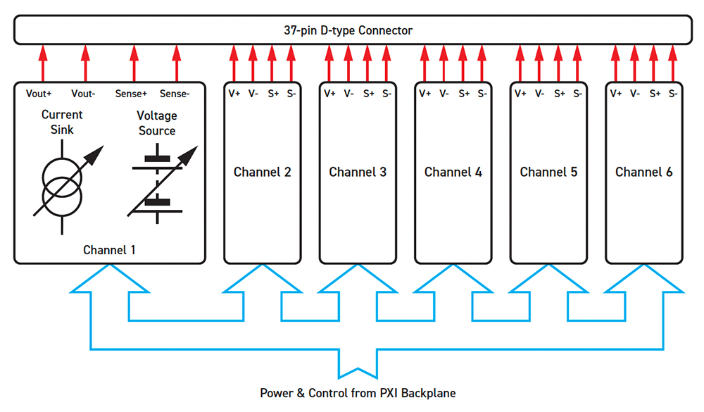
Figure 2 shows the block diagram of a multi-channel battery simulator module available in PXI (41-752A) and PXIe (43-752A). It comprises several power supply channels (two, four or six per slot) capable of supplying up to 7V and 300mA, which are isolated from one another and from system ground. Therefore, the module’s power supplies can be used to emulate a stack of battery cells. Also, each channel can sink up to 300mA to emulate a battery under charge. Each channel provides independent power and sense connections, allowing the simulator to sense a remote load and correct for wiring losses.

High Voltage Switching
High voltage switching is utilized in test systems for connecting or disconnecting signals and routing them between points, achieved through three configurations:
- Uncommitted switches (e.g., single-pole, single-throw, normally open or closed).
- Matrices that connect any input to any output.
- Multiplexers (MUXs) that connect a single input to multiple outputs.
These configurations come in various relay and connection counts, with modules capable of switching several kV, making them suitable for applications like isolation switching and breaker simulation.
High-voltage switching can be achieved using several solutions from Pickering Interfaces: over 60 PXI/PXIe modules and 28 LXI modules. For example, the 40-323-901 (PXI) and 42-323-901 (PXIe) are 14xSPST relay modules suitable for high-voltage power switching applications. They can handle current up to 0.25 A for cold switching up to 9 kVDC (9 kVAC peak) and for hot switching up to 7.5 kVDC (7.5 kVAC peak).
RTD Simulation
Temperature must be monitored at various locations in an EV, including the battery pack, motors, power inverter, charger port, and cabin. A popular and cost-effective option is the resistance temperature detector (RTD), with the PT100 being a common type with a resistance of 100Ω at 0°C. RTDs can have either a positive or negative temperature coefficient (PTC or NTC).
Simulating RTDs is beneficial since testing the design under a wide range of temperatures would otherwise require expensive environmental test chambers.
PXI-based RTD simulator modules are available from several companies. For example, Pickering Interfaces has many suitable modules for RTD simulation, including the 40-263 (with 4, 8, 12, 16, 20 and 24 channels) that can simulate the resistance range 40 to 900Ω, which equates to a temperature range of -150 to 850oC, to a resolution of less than 10mΩ. Figure 3 shows an example module.
To a lesser degree, thermocouples are also used in EVs, primarily in product development, due to their high accuracy. Their outputs, which are small voltages (a few millivolts), can be simulated. Pickering Interfaces offers PXI millivolt thermocouple simulator modules with 8, 16, 24, or 32 channels, providing highly accurate low-voltage sources. Each channel can operate across three voltage ranges to simulate any standard thermocouple type used in the industry.
Fault Insertion/Injection
The ability to insert faults during system development and verification is essential. As mentioned above, systems might need to instigate a safe shutdown or, if redundancy is built in, power re-routed if a fault is detected. This functionality needs to be fully validated.
Pickering Interfaces’ range of PXI fault insertion units is explicitly designed for safety-critical applications where the behavior of a control system, such as a BMS, needs to be thoroughly evaluated under all potential real-world fault conditions.
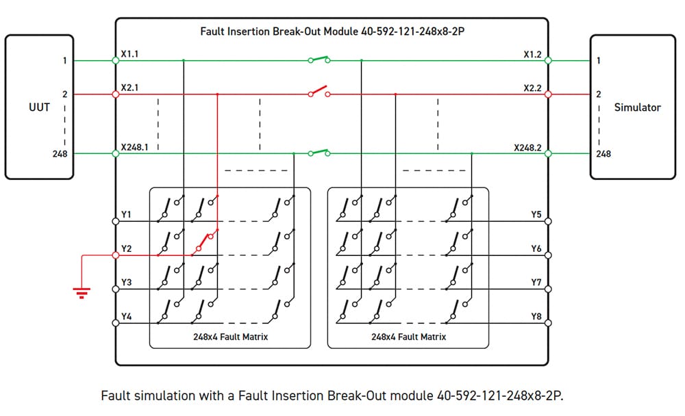
For example, the 40-592 fault insertion break-out (FIBO) is a large-scale, high-density switching matrix. It is one of a range of modules designed for applications requiring the simulation of a variety of faults in complex designs with a high number of signals/connections, such as a battery pack.
Open circuits and short circuits (to another signal/component or to the ground) are typical faults that can be simulated.

Summary
Moving from 400 to 800 V architectures offers benefits like higher performance and faster charging. However, it requires greater durability and safety. Simulation is the safest way to verify an EV’s architecture and systems, allowing for easy test conditions and results traceability. Using PXI and LXI-based test equipment provides manufacturers with an easy migration path. This enables optimizing key system components and accelerates system development through automated testing.


